
The lid of this chest is one of its most notable and distinguishing features. With the chest open it will display the panel saws, the beautiful strap hinges, and it will guide the eye down to the heart of the tool chest. When the lid is closed it’s still in full-view due to the slant of the top. For these reasons, I think this is an important piece to get right, and a step that I’ve been intimidated by since the start of the project. The issue is the width of the lid, in order to accommodate the slant of the top it will need to be nearly 16 inches wide. As I can’t easily source pine any wider than 12 inches (just another reason I wish we were back in the Northeast), I’m going to have to make the lid from two panels. My first hesitation is that using two panels will require an edge-to-edge glue joint …“weak”. Secondly, the wide lid will be liable to cupping and warping, especially since it is not joined to any other parts of the chest. After doing some research it appears there are two ways to handle this.
- Nail or screw a pair of battens running across the width of the lid and opposing the grain.
- Breadboard ends. This amounts to joining a board at each end of the lid that opposes the lid’s grain direction, similar to the battens, but an integrated piece of the lid itself.
I decided on the breadboard ends for a two reasons – one, I think the finished and pegged breadboards look really nice and two, it’ll be a challenge and hopefully next time I won’t be so intimidated by a lid…
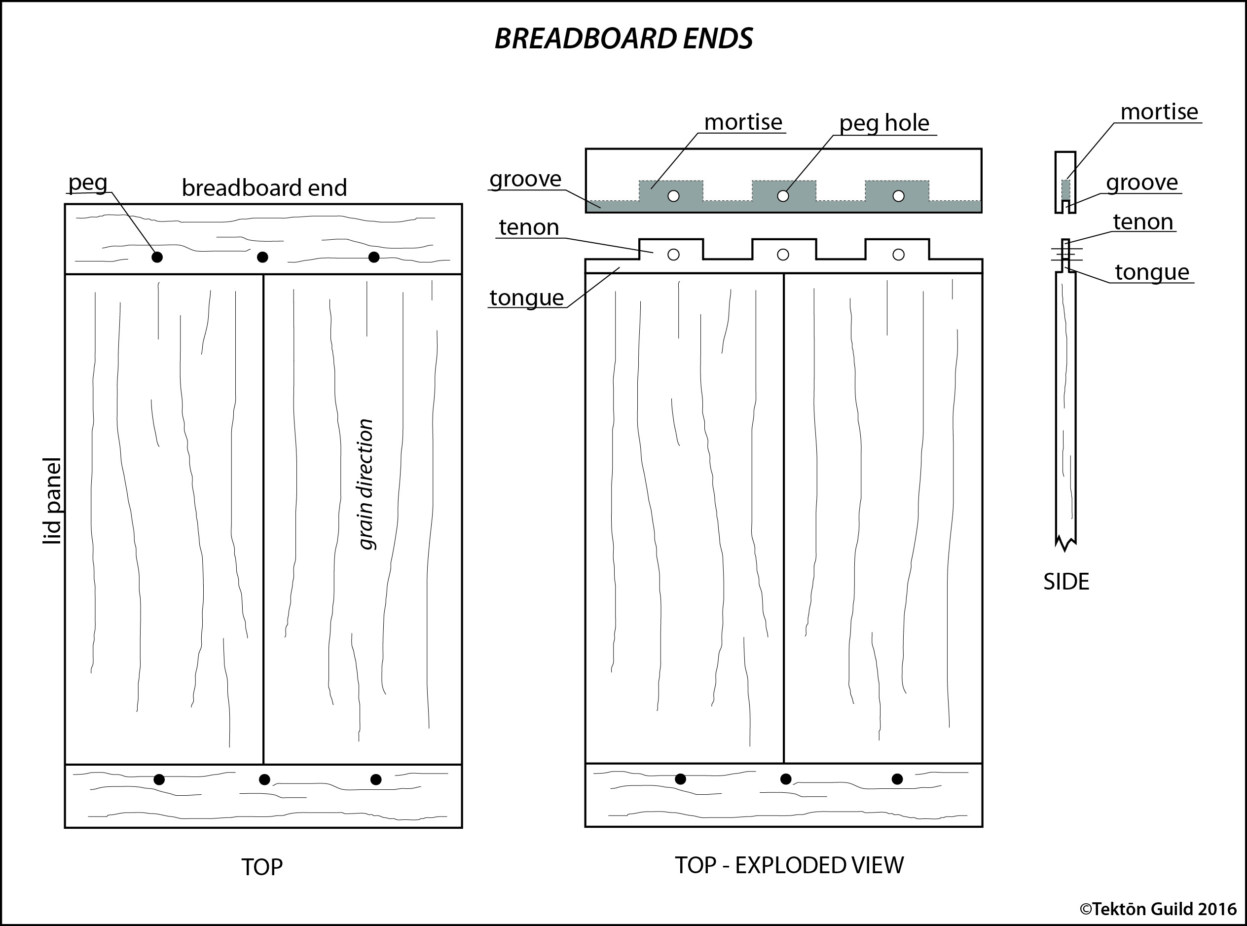
To better illustrate what breadboard ends are and how they help to counter cupping and warping of the lid I made the quick sketch below. You can see that the ends become an integrated part of the lid as they have the same thickness and width. They are joined by creating a tongue and several tenons on the long panel of the lid, these secure in a matching groove and mortises on the breadboard end. To complete the joint, the ends are drawbored and pegged through the tenons to snug things up (more on drawboring and what it is below). The joint itself isn’t glued which allows the lid to accommodate any seasonal movement without splitting, or at least that’s the hope.


I started the process by plowing the groove in the ends. The reason for starting here is that my plow-plane has a ¼” blade and instead of measuring the tenon thickness (and likely introducing error) I could fit the rest of the joinery directly to the initial groove. I set the fence on the plow-plane so that the groove would be centered on the end and started plowing.

With the groove finished I moved on to the main lid panel to cut the tongue and tenon. I determined what the required width of the tongue and tenon would be from the depth of the groove I had just plowed and adding the depth I wanted the mortises. Then using a skew-rabbet plane, I started to cut the tenons to size. I worked from each side, closely approaching my final thickness. Once I was close I switched to the shoulder plane. This allowed me to sneak-up on the correct thickness by test-fitting the joint and taking small shavings where it was still too thick.


I laid out three tenons on each end, cut the walls of the tenons with a dovetail saw, and removed the waste with a coping saw. The top of the tongue where the waste was removed was cleaned up with a little chisel work, and the board was flipped on its side to crosscut the last bit of waste on the outer tenons.

The completed tongue and tenon board was inserted into the groove on the breadboard end so I could directly transfer the width of the matching mortises. In order to expedite the waste removal of the mortises and accurately hit my depth I chucked a ¼” auger bit in my brace and augured a series of holes across the mortise.

It was still a lot of careful work to chisel out the remaining waste since the board was so narrow and the mortising is liable to split the board or the narrow sides of the groove. I only have a single mortise chisel, but luckily it’s a 1/4” as well. The mortise chisel is thicker than a normal bench chisel; its wide sides help it register in the mortise as it is driven with a mallet. This keep everything square as well as provides a little more meat for the pounding and levering that is required during mortising. As with the initial tongue and groove I alternated test-fitting and making small refinements in the mortises to get a good fit.

Once the joinery for the mortises was complete I needed to secure the ends to the main panel of the lid. The mortises and tenons will be drawbored and pegged which should give a tight fit that won’t require glue and still allow the seasonal wood movement that the joint is designed to accommodate. Drawboring is the process of slightly offsetting the holes for the pegs between the tenons and mortises so that when the pegs are driven through, the joint will be drawn tight. This requires strong, straight-grained pegs that are tapered at one end to navigate the gap left between the offset holes. I used red oak for the pegs and tapered them with one of my carving knives. This is hard to describe in words so here’s another quick sketch to help illustrate the process.


Traditionally, a set of drawbore pins are used to help draw the joint together before and during the process of driving the pegs. A drawbore pin is simply a tapered, metal rod affixed to a handle. I’ve been meaning to make a pair of drawbore pins by putting handles on a set of alignment pins used for metalworking, but haven’t quite finished that project yet. So I used the unhandled alignment pins to help with the drawboring.

A dab of glue was placed on each peg to help secure them and they were driven to with a mallet. It was a bit of guessing to get the taper right so that it would draw things tight yet still fill the hole. I was mildly successful with in my estimation; there are some gaps on the underside of the lid. The protruding bits of the pegs were then trimmed with a nifty flush cut saw, which has a flexible blade that allows for a very close and clean cut.

The breadboards and lid were cleaned up with the jointer plane and then the smoothing plane. The final step is to bevel the back to match the 30-degree slant of the sides and to cut a decorative profile around the edges known as a thumbnail profile. The majority of the bevel was quickly taken care of with the jack plane, until the last few strokes, which were finished with the jointer plane. The thumbnail profile can be created by a dedicated moulding plane, but since I don’t have one I had to cheat. I started by cutting a 1/8” rabbet around the front edge and sides of the lid with the skew-rabbet plane. I then used my block plane to round over the edge and create the thumbnail portion of the profile. I also found the shoulder plane useful for the rounding since it can cut flush to the wall of the rabbet, whereas the sides of the block plane interfere with taking a close shaving.

As you can likely gather this was an involved process and took me most of a three-day weekend, but I’m pleased with the results and glad that I choose the challenging route. No more intimidation, it’s time for a beer…
